Imaging
Meet the Omniscan Family of Imaging Sonars. Enabling explorers, researchers, and search & recovery around the world.
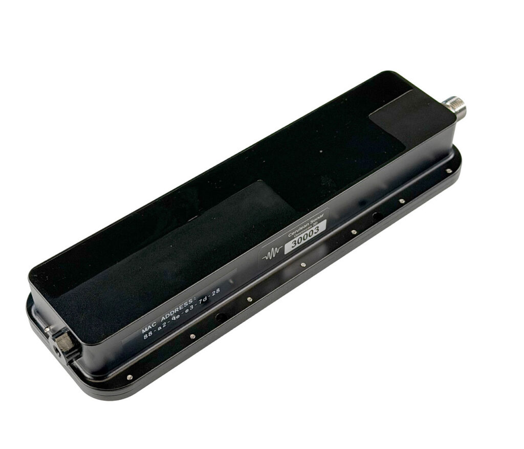
The Omniscan Family
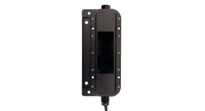
The standard Omniscan Family features a single narrow and tall sonar beam in common with conventional side scan sonars. The innovation is in the tight integration with the Cerulean SonarView application which uses position and heading information and “paints” the image in real time. In a forward scanning ROV application, you have complete control of where and how you scan by rotating the ROV. This means you can instantly focus on a specific area of interest as well as maintain exquisite situational awareness with a quick 360 degree scan.
As for image quality, think high resolution side-scan. Check out the video to see how image quality and situational awareness compare vs a very popular forward looking multibeam sonar costing 10x more.
Omniscan Specifications
| 450 Compact | 450 FS 100m | 450 FS 300m | 450 SS | |
| Price | $2990 | $2490 | $2990 | $2590 |
| Frequency (nominal) | 450 kHz | 450 kHz | 450 kHz | 450 kHz |
| Range Resolution | up to 1/1200th of range | up to 1/1200th of range | up to 1/1200th of range | up to 1/1200th of range |
| Maximum Ping Rate | 20 Hz | 20 Hz | 20 Hz | 20 Hz |
| Power | 10-30V, 10 watts max (pinging) | 10-30V, 10 watts max (pinging) | 10-30V, 10 watts max (pinging) | 10-30V, 10 watts max (pinging) |
| Data Interface | 100BaseT Ethernet | 100BaseT Ethernet | 100BaseT Ethernet | 100BaseT Ethernet |
| Internal Ethernet Switch | Yes | No | No | No |
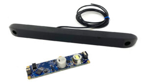
| Internal Electronics | Yes | Yes | Yes | No |
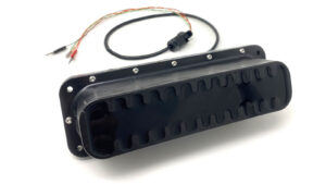
| Electrical Connection | single cable w/4 pin JST for Ethernet data + 1 wire pair for power. Options for the 3 ports including Blue Trail bulkhead connector(s). | single cable w/4 pin JST for Ethernet data + 1 wire pair for power | single cable w/4 pin JST for Ethernet data + 1 wire pair for power | PCB assembly has 3 position transducer interface, 4 pin JST for Ethernet interface, 2 pin JST for power. |
| Maximum Range | 100m | 120m | 120m | 150m |
| Beam Width | 1.1 deg | 0.8 deg | 0.8 deg | 0.5 deg |
| Beam Height | 50 deg | 50 deg | 50 deg | 50 deg |
| Vertical Beam Angle | 10 deg downward | 0 deg | 0 deg | 0 deg |
| Weight in Air | 934g | 440g | 825g | 180g (transducer only) |
| Weight in Water | 400g | -60g (buoyant) | 325g | -10g (Transducer only) |
| Max Operating Depth | 300m | 100m | 300m | 300m |